Ignition Coil Wiring Diagram : Pertronix Positive Ground Wiring. In the years when engines were a lot easier to work with a ballast resistor was used in order to prolong the life of the coil. Ignition coil ballast resistor wiring diagram with ignition coil ballast resistor wiring diagram, image size 609 x 360 px, and to view image details please click the image. Collection of simple ignition wiring diagram. Clip one end of the spark tester (service part number 19368) to the ignition cable and the other grounded to the cylinder head as shown below. Connect the voltmeter red lead to the positive (+) terminal of the coil and the black lead to a good engine ground.
Place ignition switch in the off position. Wiring diagram for ignition coil more information find this pin and more on 63 f100 wiring by ben platt. It contains both primary and secondary winding circuits. Sometimes substituted for a failed magneto coil ignition syst. It shows the components of the circuit as streamlined forms, as well as the power and also signal links between the tools.
Chevy Coil Wiring Diagram 1985 Rover 75 Fuse Box Location Furnaces Yenpancane Jeanjaures37 Fr from static-cdn.imageservice.cloud A wiring diagram is a simplified standard pictorial depiction of an electrical circuit. That's right, unhook the ignition grounding lead from the coil itself and use the spark tester. Then look very closely at the wiring to see if it's shorted to ground somewhere. It shows the elements of the circuit as streamlined shapes, as well as the power and also signal links in between the tools. This makes the procedure for assembling circuit easier. The coil is probably the easiest thing to check and therefore the first thing to check when embarking upon ignition system troubleshooting. Cylinder to cylinder variations are valuable. This tutorial will help you test the ignition coil, ignition module, and the crankshaft position sensor:
It contains both primary and secondary winding circuits.
Place ignition switch in the off position. In the years when engines were a lot easier to work with a ballast resistor was used in order to prolong the life of the coil. The wired differences matt dixon southern illinois university carbondale,. Wiring diagram for ignition coil more information find this pin and more on 63 f100 wiring by ben platt. Primary current is an available test on all types: Clip one end of the spark tester (service part number 19368) to the ignition cable and the other grounded to the cylinder head as shown below. It shows the components of the circuit as streamlined forms, as well as the power and also signal links between the tools. This applies to all old cub cadet ford jacobsen john deere wheel horse case and simplicity garden tractors. It shows the elements of the circuit as streamlined shapes, as well as the power and also signal links in between the tools. It contains both primary and secondary winding circuits. 4.3 vortec ignition coil wiring diagram source: How to properly connect this type of coil to your engine. I had a if this is a newer eng.
Wiring diagram for ignition system Because the output spark is very much higher voltage (20,000v) than the car battery (12v), it doesn't care if the battery polarity is helping or hindering by a meager 12 to 14 volts in battery potential. Heres how to put it all back together after youve torn it all apart. The coil is probably the easiest thing to check and therefore the first thing to check when embarking upon ignition system troubleshooting. The simple fix for this is to reverse the two primary wire connections on the ignition coil.
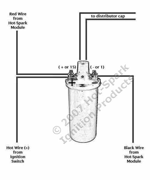
12v Ignition Coil Wiring Diagram Velvet Wiring Diagram Value Velvet Puntoceramichemodica It from www.hot-spark.com Sometimes substituted for a failed magneto coil ignition syst. If one is suspect, perform the outlined checks exactly as mentioned. Wiring diagrams for all at volovetsinfo and of course what we provide is the most best of images for club car ignition switch wiring diagramif you like images on our website please do not hesitate to. Collection of simple ignition wiring diagram. (do not disconnect wires from ignition coil). This applies to all old cub cadet ford jacobsen john deere wheel horse case and simplicity garden tractors. Ignition coil ballast resistor wiring diagram with ignition coil ballast resistor wiring diagram, image size 609 x 360 px, and to view image details please click the image. The wired differences matt dixon southern illinois university carbondale,.
If one is suspect, perform the outlined checks exactly as mentioned.
Variety of chevy 350 ignition coil wiring diagram. Cylinder to cylinder variations are valuable. Be sure to isolate the coil from the equipment wiring harness as well as the engine's wiring harness. Collection of mallory ignition wiring diagram. It shows the elements of the circuit as streamlined shapes, as well as the power and also signal links in between the tools. We have actually collected numerous pictures, ideally this image works for you, and assist you in discovering the answer you are looking for. A wiring diagram is a streamlined traditional pictorial representation of an electrical circuit. The ignition coil is nothing more that an electrical transformer. The coil primary winding contains 100 to 150 turns of heavy copper wire. Basic ignition system wiring diagram. I.ytimg.com read interactive wiring diagram for your needs read wiring diagrams from negative to positive and redraw the routine like a straight range. Led rgb mod installation instructions basic wiring diagram manualzz. This wire must be insulated so that the voltage does not jump from loop to loop, shorting it out.
Home | diagrams by model | honda engines | engine | gx | gx. Diagram small motor coil wiring full version hd quality softdiagram zanzibarbeach it how to test and repair ignition system problems briggs stratton magneto kill terminal electronics forums stens 298968 460 006 diagrams damon challenger source auto5 yenpancane jeanjaures37 fr engine wire bege what does the ignitor on a jd f 525 do havwe machine no spark but cranks… read more » This tutorial will help you test the ignition coil, ignition module, and the crankshaft position sensor: It shows the elements of the circuit as streamlined shapes, as well as the power and also signal links in between the tools. It shows the components of the circuit as streamlined forms, as well as the power and also signal links between the tools.
Cylinder 2 Ignition Coil Wiring Diagram 2002 Ls430 Clublexus Lexus Forum Discussion from cimg2.ibsrv.net Basic ignition system wiring diagram. It shows the components of the circuit as streamlined forms, as well as the power and also signal links between the tools. The simple fix for this is to reverse the two primary wire connections on the ignition coil. Collection of mallory ignition wiring diagram. Because the output spark is very much higher voltage (20,000v) than the car battery (12v), it doesn't care if the battery polarity is helping or hindering by a meager 12 to 14 volts in battery potential. Variety of chevy 350 ignition coil wiring diagram. Then look very closely at the wiring to see if it's shorted to ground somewhere. Clip one end of the spark tester (service part number 19368) to the ignition cable and the other grounded to the cylinder head as shown below.
Wiring diagram for ignition system
This wire must be insulated so that the voltage does not jump from loop to loop, shorting it out. Accuspark wiring diagrams ignition system basics matt dubanoski 12 volt coil and distributor basic diagram ball switch 3 typical car starting t x ford 2n electronic farmall tractor conversion systems a short course converting to one wire alternator led rgb mod installation instructions how motorcycle read your boat schematic. Club car ignition coil wiring diagram gas opel gt ignition switch diagnosis. In the years when engines were a lot easier to work with a ballast resistor was used in order to prolong the life of the coil. How to properly connect this type of coil to your engine. I.ytimg.com read interactive wiring diagram for your needs read wiring diagrams from negative to positive and redraw the routine like a straight range. Home | diagrams by model | honda engines | engine | gx | gx. Primary current is an available test on all types: Collection of mallory ignition wiring diagram. Led rgb mod installation instructions basic wiring diagram manualzz. A wiring diagram is a streamlined traditional pictorial representation of an electrical circuit. Basic ignition system wiring diagram. Testing the coil or armature step 1 :
Share :
Post a Comment
for "Ignition Coil Wiring Diagram : Pertronix Positive Ground Wiring"


Post a Comment for "Ignition Coil Wiring Diagram : Pertronix Positive Ground Wiring"